In this post I’ll present a way to turn the stm32l476-discovery board into fully functional radio receiver using a single additional component and making minor modifications to the board.
The presented solution is a radio receiver done entirely in the digital domain. The incoming RF signal is directly sampled by the stm32l4’s internal 12-bit ADC and all further processing was implemented in the source code.
This makes this project into a nice learning platform for all those who wish to enter the world of digital communication. Couple of basic concepts were employed, such as:
- Complex signal mixing
- Signal filtration using purely software IIR filters and hardware
CIC filters - AM demodulation
Thanks to the outstanding performance of the Cortex-M4F core and MCU’s peripherals as implemented by the ST a sampling rate of 2.5Msps was achieved while keeping the Core clock at 80MHz and still leaving time for more processing (basic AM receiver uses around 70% of CPU time).
Let’s dive into the signal path step by step.
1. RF Input
This is where we need to modify the PCB a little since in case of the stm32l476-disco ST did not leave any free pin with analog capabilities I’ve decided to liberate the PA0 from its original function (joystick center contact) and for that C43 and R55 need to be removed from the board. After doing that we are left with PA0 that goes directly to the input pin of the MCU.
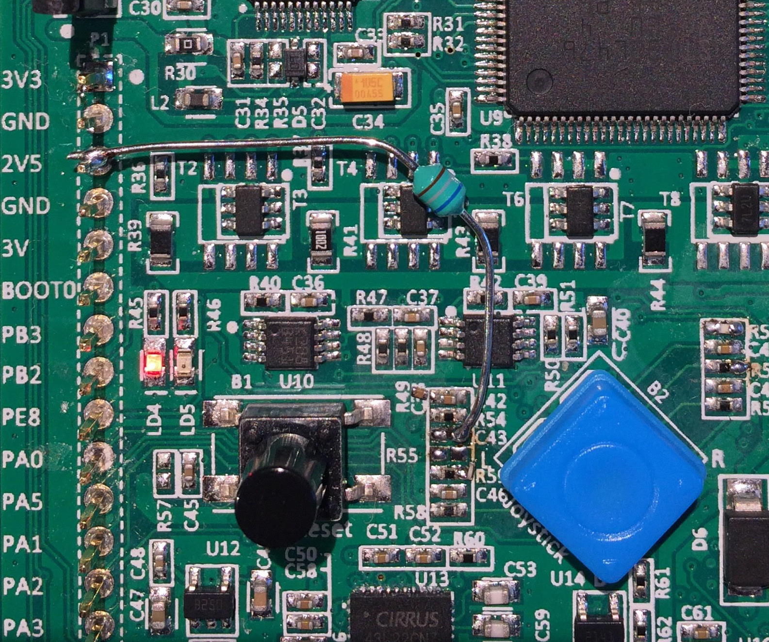
After all of these steps are done we are now officially ready to sample the input signal. We do that at mentioned 2.5Msps, 12-bits per sample. This is well within the spec of the ADC (the specified limit is 5.5Msps@12bits per sample).
2. 1st stage mixer
After the signal has been sampled we need to somehow tune in to the frequency of interest and limit the sampling rate. 2.5Msps at 80 MHz leaves you with only 32 cycles for the complete processing of a single sample which is not very much to say the least if you take into account that some demodulation schemes require methods that are computationally intensive.
The only way to mitigate this is to bring the signal of interest to the DC, apply low-pass filtration and decimate so that we end up with manageable sampling rate.
The process of shifting the signal to near-DC is called mixing. Mixing is done by multiplying the input signal with a complex local oscillator (LO) which in plain words means multiplying the input data with sine and cosine that oscillate at frequency of our choosing.
Why bother with complex multiplication and not stick to the plain old multiply-by-sine-only technique? Switching to complex numbers allows to take the full advantage of the concept of negative frequencies which in certain situations (like demodulation of signals that have non-symertrical spectrum like, for instance, SSB) can make things A LOT easier.
If you know little about the processing of complex (a.k.a analytical) signals “Quadrature Signals: Complex, But Not Complicated” (by Richard Lyons) will make for an excellent read for you. Please take a moment to find it on the web and digest it.
The realization of the complex mixing was done by splitting the RF signal into two paths and multiplying with elements of two pre-computed look up tables: \(cos(t)\) and \(-sin(t)\) that constitute the Local Oscillator.
The negative sign in front of the \(sin(t)\) denotes that we are multiplying with the complex numbers in form \(cos(t) – jsin(t)\) which will cause frequency subtraction, thus bringing the positive frequency f to DC, and moving the DC to -f, etc..
I’ve prepared the main (constant) cosinusoid look-up table (LUT) to have 256 entries, allowing for 128 different frequency steps (bands) of the Local Oscillator. The entries are scaled by \(2^{30}\) and are represented as 32-bit signed integers. Since sine is just a shifted version of cosine this array can be used to initialize both the \(cos(t)\) and \(-sin(t)\) multiplication arrays.
Frequency selection is done by precomputing the \(cos(t)\) and \(-sin(t)\) (of length identical to the length of LUT) arrays in such a way that we put every (n-th entry % length(LUT)) from the main LUT into \(cos(t)\) and every ((n-th entry + length(LUT)/4) % length(LUT)) from the main LUT to the \(-sin(t)\), where n is the LO band (or frequency step), that goes from 0 to length(LUT) / 2. We do that till we fill the \(cos(t)\) and \(-sin(t)\)
If, for example, LUT was only 8 entries long then if we would like to select the LO to output frequency step of 3 the \(cos(t)\) array would consist of following LUT entries: [#0, #3, #6, #1, #4, #7, #2, #5] and \(-sin(t)\) would be like [#2, #5, #0, #3, #6, #1, #4, #7]. The frequency of the step 3 would be equal to: \(2.5Msps * 3 / length(LUT) = 7.5/8 = 937.5kHz\). Selecting step of 2 would yield [#0, #2, #4, #6, #0, #2, #4, #6], [#2, #4, #6, #0, #2, #4, #6, #0] respectively. For the zeroth frequency step we have a constant of 1 (beacuse #0 in LUT is 1) for the \(cos(t)\) and constant of 0 (because #2 is equal to 0 in LUT) for \(-sin(t)\).
In case of 256 entry LUT we can generate output frequencies that are spaced every \(2.5Msps/256 = 9765.625Hz\). Still not fine enough to provide good tuning resolution, but doubling the precision would require to make the cos(t) and -sin(t) tables twice as big That would eat up quite a large portion of the RAM. If one was aiming for a resolution of 10Hz (very reasonable especially for SSB reception, then the array would have to be 250000 entries long – completely not practical). I’ll deal with the problem of fine tuning later.
The result of multiplying the RF samples with \(cos(t)\) is called “In-Phase” (I) channel and the product of RF and \(-sin(t)\) is the “Quadrature” (Q) channel.
All in all this stage of processing is the most time consuming since we operate at full 2.5Msps doing two multiplications (with cosine and sine), truncation with rounding to limit the number of result bits for the next stage. This is the main reason why I’ve opted to use two “plain” arrays for \(cos(t)\) and \(-sin(t)\): to allow for the fastest data processing possible without any additional “number crunching” at the expense of RAM memory.
3. Decimation by 64
After we brought the signal to the near-DC we can apply the low pass filtering. Since we are still processing at 2.5Msps normal filtration methods using FIR or IIR are still beyond the scope of what this MCU has to offer in terms of processing power, but if the decimation by 64 could be achieved then the sampling rate would fall to 2.5Msps/64 = 39062.5sps which is very manageable and provides the theoretical bandwidth limit of the input signals of the 39kHz: (2 channels [I,Q] * Nyquist Frequency = \(2 * 1.25MHz/64 \approx 39kHz\)) This is much more than any Long Wave/Medium Wave station would need.
Thankfully, STM32L476 comes with build-in CIC (Cascaded Integrator Comb) decimation filter bank that happen to be just the right tool for the job. The peripheral that the CIC is contained within is called DFSDM. It it most often used in conjunction with MEMS microphones that output the PDM signal which is a 1-bit audio signal (so only 1 bit digital “bus” is required for the data, very convenient), highly oversampled at let’s say ~3Msps that then gets filtered and downsampled which results in a bit growth and sampling rate reduction.
Bit growth is the number of bits that output data gains with respect to the input data. This is a consequence of gain that is inherent to the CIC filters.
DFSDM allows for flexible configuration of the filter and may use the DMA channels for pushing the data in and out of the filter block. The performance is great: only 75us @ 80MHz clock are needed to filter 1024 samples provided by the ADC after the 1st stage Mixing. What’s even better is that this can be run asynchrnonously: user may configure the data feeding/fetching DMA’s, start the process and go back to processing the previously filtered data chunk.
If you want to know more about the CIC filters I advise you take a look at this paper called “Small Tutorial on CIC filters” by J. Arzi and at this Wikipedia page . In any case: we have two things to set up while working with CIC filters:
- Filter order – N
- Decimation rate – R
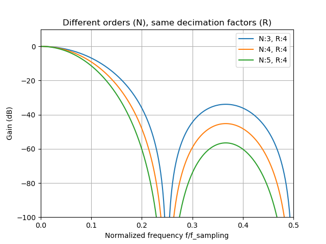
Filter order determines the “steepness” of the filter response, or how “sharp” the filter response looks. One needs to be careful though: the higher the order is the more droop will be present in the pass-band. Bit Growth scales linearly with order. Below you can see the response of the filters that have the same decimation rate but different orders:
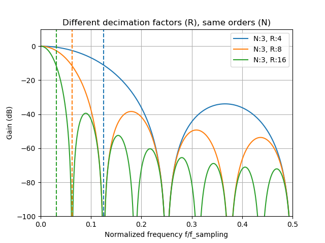
Decimation rate tells us what will be the reduction in sampling rate after the filtration. Ex. decimation factor of 2 means that we’ll end up with half as many samples as were provided at the filter input. This also influences the bit growth, but this time logarithmically (log2). Below you can see how the decimation rate impacts the filter response for same-order filters:
Total bit growth formula is as follows: \[bit\_growth=\lceil filter\_order*log_{2}(decimation\_factor)\rceil\]
And the overall (normalized, i.e. divided by the bit-growth) filter response magnitude is given by: \[|H(f)| = \left|\frac{sin(\pi*f*R)}{sin(\pi*f)*R}\right|^{N}\] where \(f\) is the relative (in relation to the input data sampling rate) frequency: \(f = f_{true}/f_{sampling} \) so it’s 0.5 for Nyquist frequency.
CIC filters within DFSDM use 32-bit wide words so we need to keep the bit growth at a level such that output samples do fit into 32 bits. Since we need to have the decimation rate of 64 we get the 6 bits of gain out of it per every filter order. That leaves us with the filter order = 3, which results in total bit gain of 3 * 6 = 18b. The maximum input data width is then 32b – 18b = 14 bits. This information can be used to adjust the truncation and rounding in the mixing stage, so that the mixer uses the full 14 bits.
Since the mixing stage produced two data streams I, Q we need to employ 2 CIC filter units. DFSDM0, DFSDM1. The datasheet for the stm32l476 gives a lot of information about how to fetch the data out of the filter using the DMA but little-to-none information about how to put the data into the filter unit. Thanks to the trial and error I’ve discovered that you can configure any DMA channel for the Memory-To-Memory transfer and point the destination pointer to the filter’s input data register. The CIC does not mind that the data transfers occur at the full speed of the DMA engine.
The output data register is 24-bits long, but have no fear DFDSM offers a capability of applying bit shift and offset correction to every output word, so we order it to do the right shift of 8, so that the internal 32-bit wide words fit into the 24-bit output register.
24 bits happens to be exactly the number that floating point numbers (the one that the core uses) employ to represent the mantissa (23 actual bits + the sign bit) so that makes the conversion not to cause the precision degradation and switching to floats will make further processing steps much more convenient to implement.
This is exactly what I’ve implemented so the overall result is: two channels I,Q of floats that come at the pace of 39062.5sps.
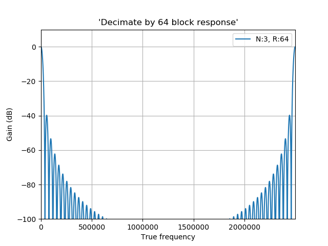
Above you can see the overall response of the Decimation by 64 block. This block lets the signals at DC, 2.5MHz, 5MHz, etc.. go through undisturbed. This is why the input signal filtration is important, but since we are cutting corners here and we want to receive anything I decided to refrain from using it.
Keep in mind that this filter is employed after the mixing, so if the mixer’s LO is tuned to 1MHz then we’ll hear the signals at 1MHz, 3.5MHz (80m amateur band, very convenient), 6MHz, etc.. up to the bounds of the ADC response.
Just to give you some idea: I did some testing: The radio was tuned to 225kHz and could still receive signals from my Signal Generator tuned to \(225kHz + 16*2.5MHz = 40.225MHz\) and \(-225kHz + 16*2.5MHz = 39.775MHz\). This confirms three things:
- Nyquist was right about the sampling theorem
- STM32 ADC has a nice analog bandwidth.
- If you want to make this into a serious radio receiver you really need to consider adding the analog filter before the ADC.
4. 2nd stage mixing
Now let’s address the lack of precision in tuning presented in 1st stage mixing. After the decimation we are now at 39062.5sps, and since the frequency step size in LO is directly proportional to the sampling rate then by employing the same NCO scheme as in the 1st stage mixing we end up with the resolution of \(39062.5sps / 256 \approx 152.58Hz\), far better than 9kHz. This means that the maximum frequency tuning error will be around \(152/2 \approx 76Hz\).
But why stop there: we can quite easly precompute the LUT so that it has let’s say 1024 entries, thus providing the tunning resolution of \(39062.5sps / 1024 \approx 38.14Hz\) which gives the maximum tunning error of ~19Hz. Good enough even for the SSB. To limit the RAM memory footprint we simply fetch the appropriate entries from the constant LUT array. We are no longer afraid of complex memory operations since after the decimation we are way down in terms of the sampling rate.
5. Decimation by 4
There is a story behind this step: For my everyday work I use the Dell XPS laptop which has no audio input (at least not an easily accesible one) and since I wanted to record the actual IQ output of this receiver (just to prove that it works and for debugging) I thought that I can go around that by sending the audio samples using USART, with base64 encoding just so to keep the “protocol” in text mode, I know, I know, lots of room for optimization..)
Quick, back-of-the-envelope calculation reveals that 39062.5sps data streams, two channel I,Q using floats require \(4B * 2 * 39062.5sps =312kB/s. \) Base64 adds about 4/3 to the overhead so that leaves us at 416kB/s. USART uses 10b per every byte sent, so we end up with minimal theoretical baudrate of 4160000. This is perfectly manageable by the STM32 but not so by USB<->USART dongles, at least not by the one that is incorporated in the on-board STLinkv2.
So I needed to reduce the data rate, and a factor of 4 seemed reasonable, leaving me with 1040000 in terms of baudrate and 9.76kHz in terms of signal bandwidth.
6. Demodulation
Only the AM demodulator was implemented since the AM broadcast stations have the greatest signal strength, which is important because we don’t have any signal conditioning nor gain blocks before the ADC.
To improve the selectivity a 2-stage second-order-system (or sos, or biquad if you like) low pass IIR filter is put in front of the demodulator.
After that we take the square root of the sum of squares of the I and Q samples \(\sqrt{I^2+Q^2}\) just so as one would like to calculate the magnitude of the complex number \(I + jQ\). That magnitude is the audio signal itself.
To get rid of any DC offsets a high pass filter is applied to the audio signal that removes anything below 20Hz.
The audio data is then converted from floats to 24-bit signed, fixed point numbers so that it can be fed to the on-board DAC via the SAI1A peripheral. The sampling rate (still at 9.76ksps) seems kinda odd as far as the audio processing industry standards go, but the DAC doesn’t seem to mind that at all.
Now we’ve finally reached the audio jack!
User Interface
This board comes with the LCD display and the Joystick. LCD displays the frequency. Joystick allows for volume control (up-down, 1dB steps) and frequency control (left-right, 1kHz steps).
Source Code, Binaries…
The code is held in a repository on GitHub. In the Release section there are some prebuilt binaries, that you can drag-and-drop on the stm32l476-disco board thanks to the STlink implementing a Mass Storage Device look-alike interface.
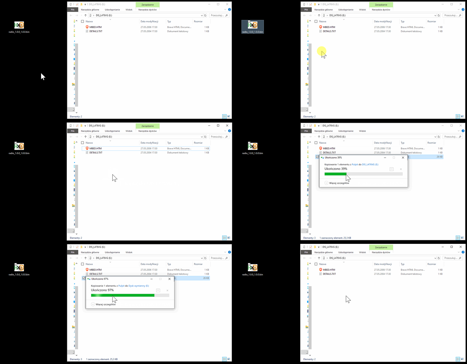
If you want to build the code yourself then perhaps you should consider using the Docker build-machine approach which I’ve presented here
DEMO
This is recorded while the RF was provided by the MiniWhip antenna. You can find the recipe on how to build one online. Just googl… duckduckgo it online. You can be fine with long, random wire antennas if you keep them far enough from any sources of radio interference (switching mode power supplies, etc.)
For the sake of making this video I’ve soldered the crappiest speaker I could find in my parts stash directly to the on-board headphone jack socket contacts.
Enjoy.